| Messiah Version 5
Main Board
Installation Diagrams |
I have verified that the following installation
diagrams below will work with all New Zealand released Version 5 main boards. The
Version 5 main board will normally be fitted in the SCPH 30002R.
To view some installation photos - click
here
Any questions etc - Email Andrew at:
messiah@fatcat.co.nz
Back to the Messiah Page |
| |
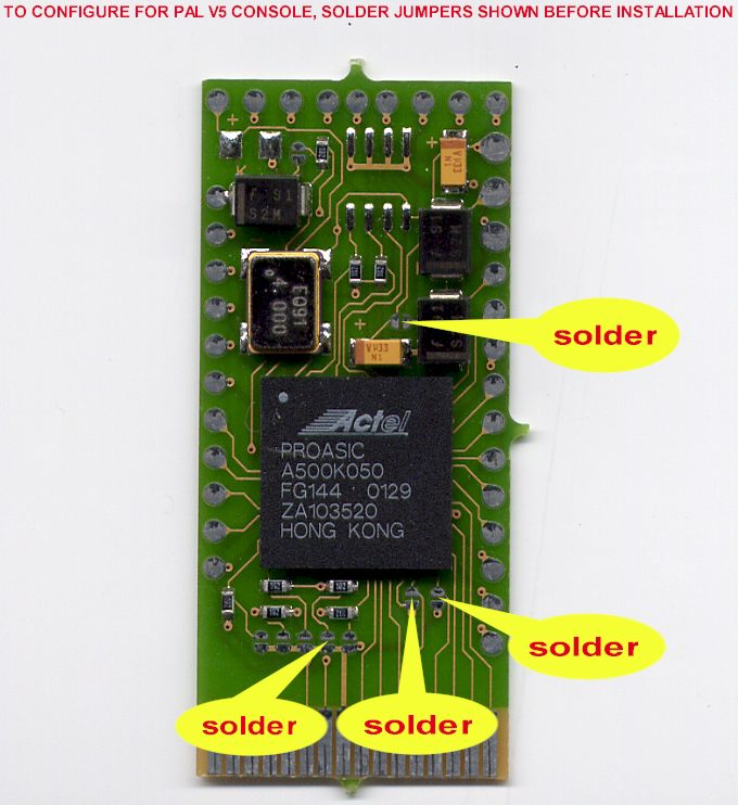
| Configuration Jumper
Settings |
|
|
|
Important: Do this first before you
start your install. Ensure that you solder all 4 jumpers. Failure to do so
may damage your Messiah chip.
|
| |
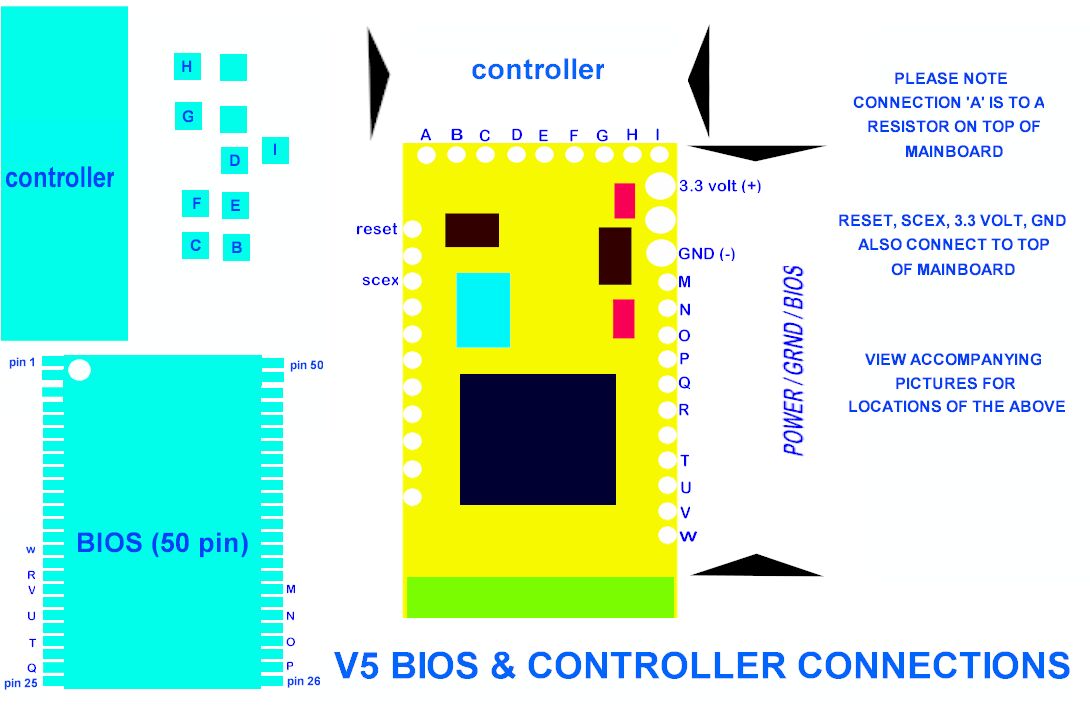
| Messiah Connection
Points |
|
|
Pictorial view of the Messiah connection pads
and the associated points on the Bios and Controller chips. Use this diagram
to check and recheck that you have soldered the wires to the correct
points.
|
|
|
| Messiah Location
& Ground Point - Top Side of Main Board |
|
|
|
The Messiah is stuck down with double sided
tape onto the open space on the topside of the main board. You can't miss it
- it's the only bit of real estate left where the chip can fit nicely onto
the main board. For the Ground point use light hook-up wire.
|
| |
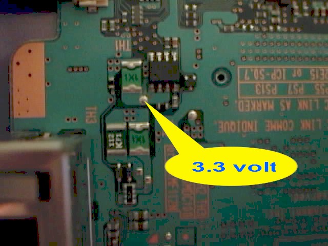
| Power Connection
Point - Top Side of Main Board |
|
|
|
This connection point are located on
the top side of the main board at the back left by the AV port connector. Use light hookup wire for
this connection.
|
| |
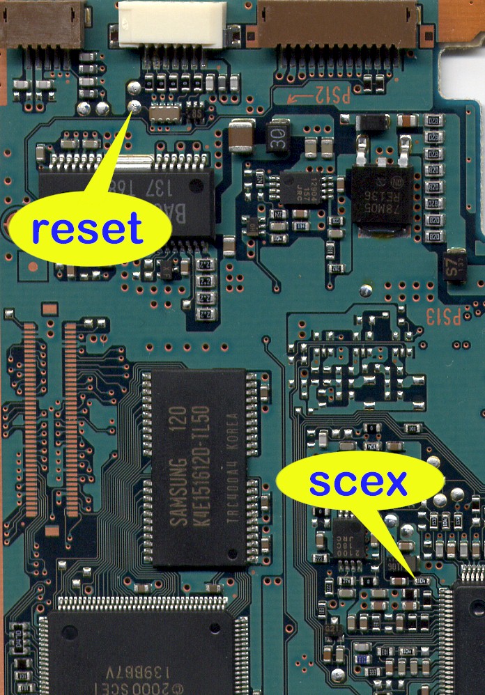
| SCEX & Reset Connection Points -
Top Side of Main Board |
|
|
|
These 2 connection points are located on the
right hand side of the top
side of the main board. Use 30swg wire wrap wire for these 2 connections.
|
|
|
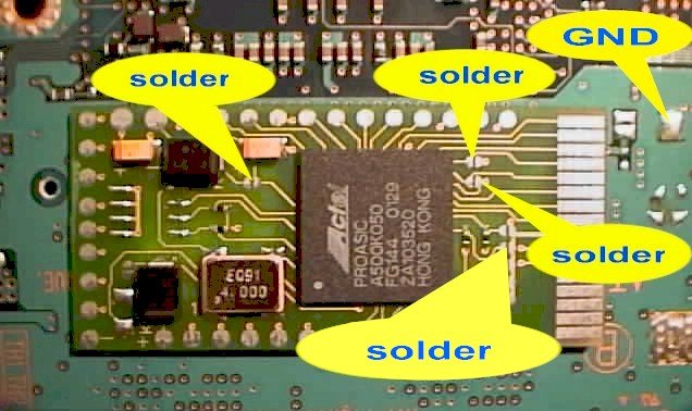
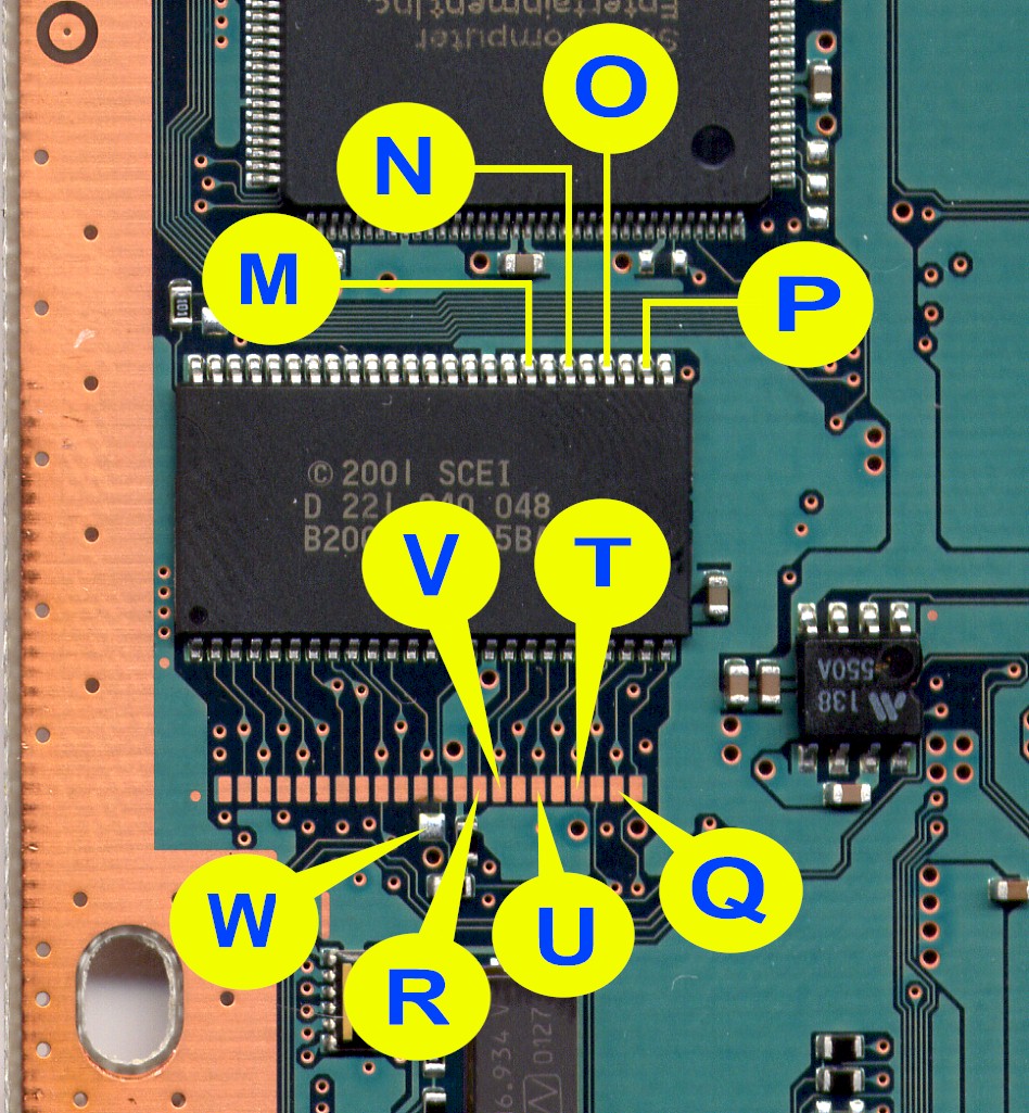
| Bios Chip - Top
Side of main board |
|
|
|
The Bios chip is located about the middle
of the back edge on the top side of the main board. Use 30swg wire wrap wire for these
10 connections.
|
|
|
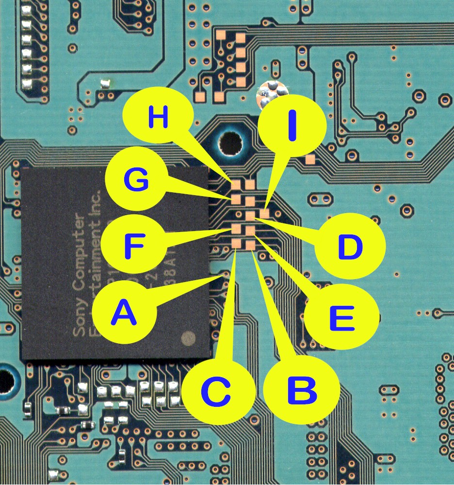
| Controller Points
- Bottom Side of Main Board |
|
|
|
The Controller chip located on the bottom side
of the main board. Use 30swg wire
wrap wire for the 8 (B, C, D, E, F, G , H and I) connections to the Controller chip and
feed the wires through the hole out to the top side of the main board. For
point "A" I use the alternative connection on the top side of the
main board - see diagram below. As you can see they are relatively problem
free connection points for the Controller chip compared to the Version 3 and
4 main boards.
|
|
|
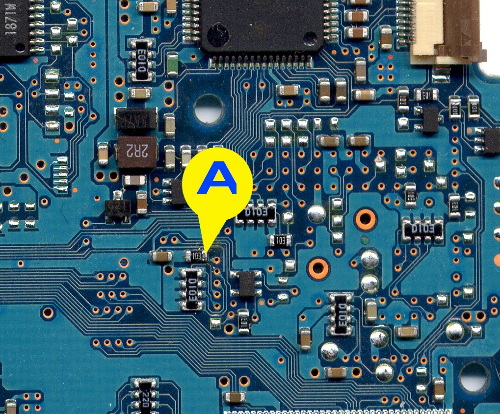
| Alternative
"A" Point -
Top Side of Main Board |
|
|
|
Point "A" is located near where the
wires from the Controller chip on the bottom side exit through the hole on
the top side of the main board. This is is the alternative connection point
for "A" and it allot easier to connect to.
|
|
|
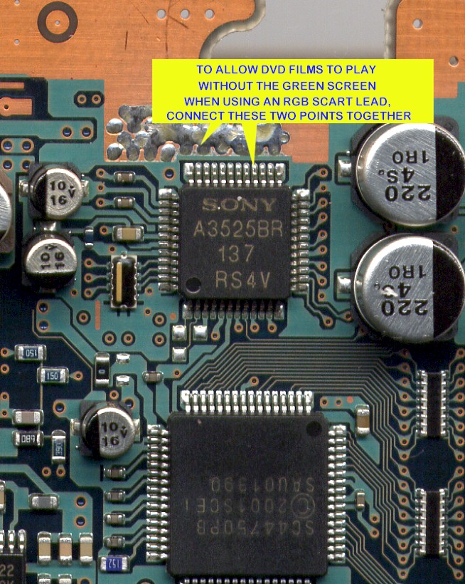
| RGB Fix -
Top Side of Main Board |
|
|
|
RGB Fix: Is
required if you intend on using a SCART/EURO cable instead of the standard
AV cable. SCART/EURO connectors are general more associated with the
Europe/UK TV systems. If you do not do this you may end up with a green
picture on your TV when viewing DVD movies. I only do this if customer wants
it.
|
|
|
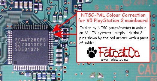
| NTSC-PAL Colour
Correction Fix -
Top Side of Main Board |
|
|
|
NTSC-PAL Colour Correction: (bottom part
of the diagram) is required if you intend on play NTSC (USA/Japan) games or
view NTSC movies. Simply just solder across the 2 pins. I do this as
standard on all installations. If you do not do this fix NTSC games will be
displayed in Black and White on PAL TV's unless you have a nice NTSC
compatible TV system :o)
|
|
|