| Messiah Installation
Pictures |
Below are photographs of some of the various
Messiah installs that I have carried out when I started to install the
Messiah chip in Jan 2002. Just click
on the thumbnails for a larger photo.
Return to the Messiah Page |
| |
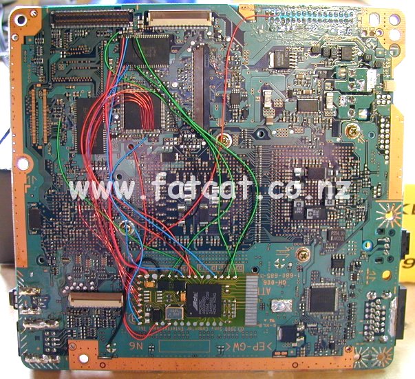
| SCPH 30002 - V3
Mainboard - No Gap Bios on top |
|
|
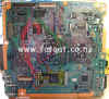 |
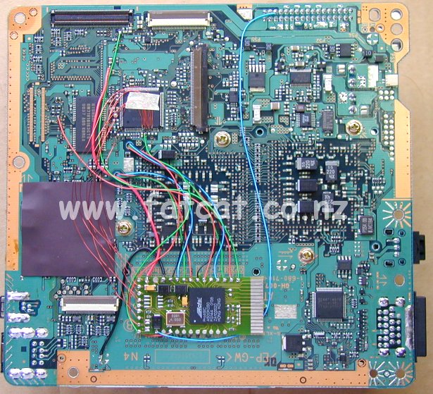
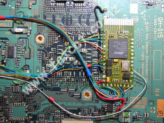
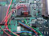
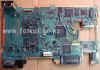
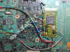
This
photo of the mainboard (before the wires were hot glued and
insulated) shows the location of the Messiah chip and the various
connection points for the controller chip, bios chip and the other
connection points. All connection points for this board are located
on the top side except for the SCEX connection which is on the
bottom side of the board. I used hookup wire for the +3.3VDC and GND
points and I used 38swg enamel wire for 8 of the 9 controller
connections and all remaining connections I used 30swg wire wrap
wire. |
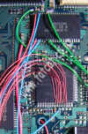 |
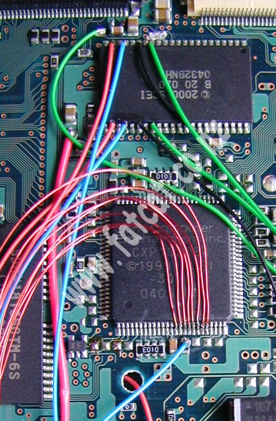
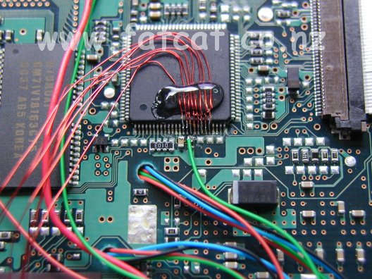
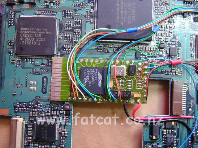
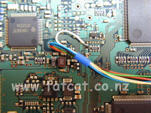
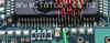
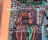
This
photo shows a close-up of the connection points for the controller
chip at the top of the photo and no-gap bios chip at the bottom of
the photo. The red wire disappearing into the hole at the bottom of
the photo is the SCEX wire. This photo you can see clearly the three
different types of wire I used in this installation. The thicker red
wire on the left is the 3.3VDC connection, the lighter red, green,
blue and black wires are the 30swg wire wrap wire and the very thin
reddish wires are the 38swg enamel wire. |
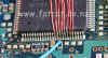 |
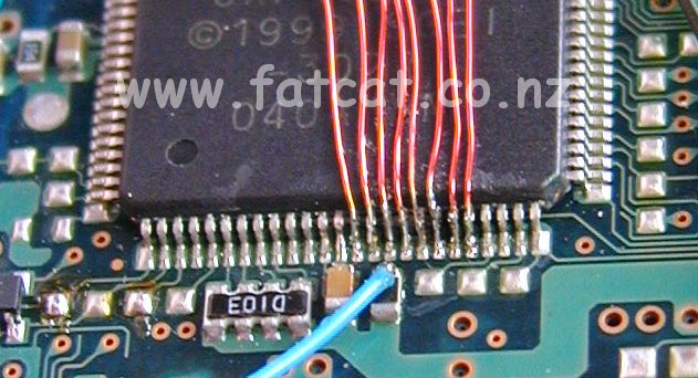
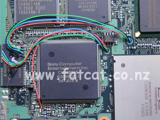
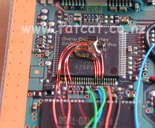
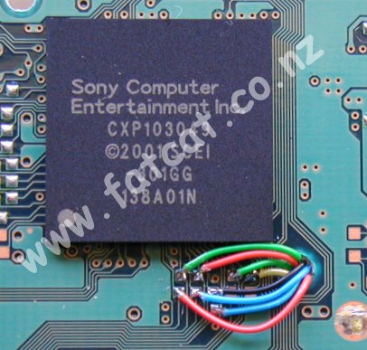
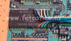
A
extra close-up shot of the controller connections. This is not for
the faint hearted and it is very essential that you use the correct
equipment to carry out the soldering of the wires to the legs on the
controller chip. The blue wire is the 9th connection point for the
controller chip. |
|
| |
| SCPH 30002 - V3
Mainboard - Gap Bios on bottom |
|
|
|
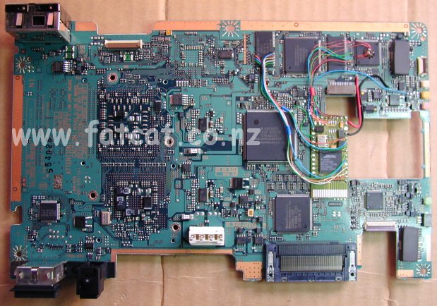
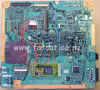
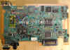
This
photo of the mainboard (before the wires were hot glued and
insulated) shows the location of the Messiah chip and the various
connection points for the controller chip and other connection
points. All connection points for this board are located on the top
side except for the 8 Gap Bios chip connections and the SCEX
connection which are on the bottom side of the mainboard. I used
hookup wire for the +3.3VDC and GND points and I used 38swg enamel
wire for 8 of the 9 controller connections and all remaining
connections I used 30swg wire wrap wire. |
|
This
photo shows the connections for the controller chip at the top of
the photo. The wiring disappearing into the two holes at the bottom
of the photo are for the Gap Bios and the SCEX connections on the
underside of the mainboard. |
|
A
close-up photo of the connections points for the controller chip
using 38swg enamel wire. |
|
This
photo shows the underside of the mainboard with the Gap Bios on the
left hand side and the SCEX connection point at the bottom of the
photo and the wiring disappearing through the two holes on the right
side and appearing on the top side of the mainboard. |
|
A
close-up photo of the 8 Gap Bios connection points and SCEX
connection. There is also a No-Gap variant of the Bios located in
the same location, make sure that you use the correct diagram as the
connect pint are different. I will add a non-gap picture soon. |
|
| |
| SCPH 35002 - V4
Mainboard - Gap Bios |
| |
 |
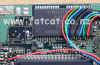
This
photo of the mainboard (before the wires were hot glued and
insulated) shows the location of the Messiah chip and the various
connection points for the controller chip and Bios and the other
connection points. All connection points for this board are located
on the top side of the mainboard. I used hookup wire for the +3.3VDC
and GND points and I used 38swg enamel wire for 4 of the 9
controller connections and all remaining connections I used 30swg
wire wrap wire. |
 |
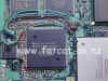
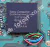
A
close-up photo of where the Messiah chip is mounted on the
mainboard. |
 |
A
close-up photo of the connections to the controller. 4 of the
connection points are onto the controller chip using 38swg enamel
wire with the remaining 5 connections using 30swg wire wrap wire and
connecting to a component and onto tracks (pass-thru's) on the
mainboard. A fibre-glass pen is required remove the solder resist
from the tracks for easier soldering connections. |
 |
A
close-up photo of the 10 Gap Bios connection points using 30swg wire
wrap wire. |
|
| |
| SCPH 30002R - V5
Mainboard - No Gap Bios |
| |
 |
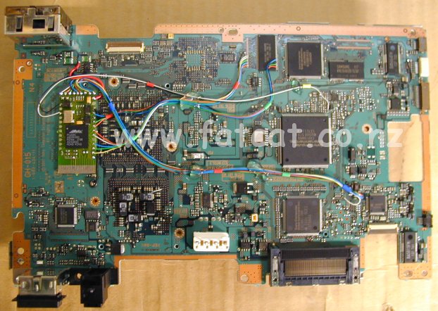
This
photo of the mainboard (after the wires were hot glued but before
insulating) shows the location of the Messiah chip and the
various connection points for the Bios chip and other connection
points. All connection points for this board are located on the top
side except for the 8 of the controller chip connections which are
on the bottom side of the mainboard. I used hookup wire for the
+3.3VDC and GND points and I used 30swg wire wrap wire for all other
connections including the controller chip.. |
 |
A
close-up photo of the Messiah chip location. |
 |
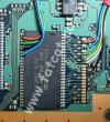
A
close-up photo of the 8 connection points for the controller chip on
the underside of the mainboard and passing through the hole and
appearing on the topside of the mainboard. The 9th controller
connection point is on the top-side. As you see you do not need to
contend with having to solder on to the legs of the controller chip
due to a change in the package of the chip. |
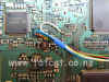 |
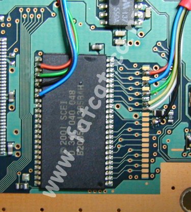
A
photo of the 8 wires appearing on the topside of the mainboard from the controller
chip on the underside of the mainboard. The white wire is the 9th
connection point for the controller chip. |
 |
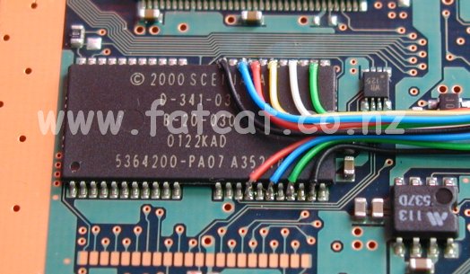
A
close-up photo of the No-Gap Bios on the topside of the mainboard. |
|