IMPORTANT: READ THIS
GUIDE THOROUGHLY BEFORE DISASSEMBLY! Please read Disclaimer Any questions relating to this guide please email techsupport@fatcat.co.nz |
Disassembly Guide for PlayStation Model SCPH 100x.
IMPORTANT: READ THIS
GUIDE THOROUGHLY BEFORE DISASSEMBLY! Please read Disclaimer Any questions relating to this guide please email techsupport@fatcat.co.nz |
| Identifying your model of PlayStation | |||||||||||||||||||||||
|
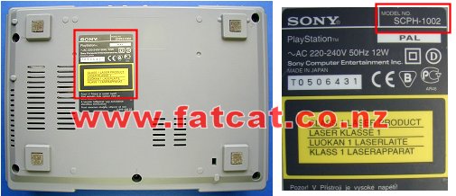
Before dismantling your PlayStation turn it over and look at the label on the bottom of the case as shown below. On the top right corner of the label it will indicate what model you have. This guide is for the model SCPH 100x, where x is either 2 (PAL, NZ/AUS/UK), 1 (USA) or 0 (JAP). If this model number is different do not use this guide. All New Zealand and Australian models will be marked as SCPH 1002
|
|||||||||||||||||||||||
| Minimum equipment required | |||||||||||||||||||||||
|
Philips #2 or Medium Philips head screwdriver. Container to place screws etc in Clean Work Area Time - Take your time |
|||||||||||||||||||||||
| Step 1: Removal of the top half of the case | |||||||||||||||||||||||
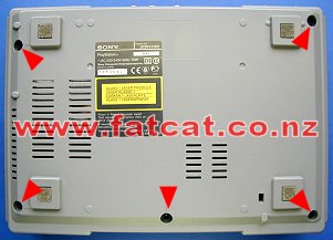
| Unplug all cables, controllers, memory cards etc from PlayStation. Remove any CD from PlayStation. Turn PlayStation over and remove the FIVE Black screws as indicated by the Red arrows that hold the 2 halves of the case together using a Philips screwdriver. |
|
||||||||||||||||||||||
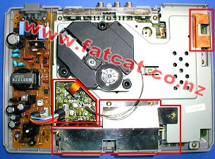
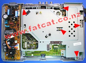
Turn PlayStation back over and lift away the top half of the case and the little cover for expansion port (if fitted), which is at the back right. Now you should see what is shown in the photo. The Red box on left hand side contains the Power and Laser Drive cables. The Red box at bottom centre is the Controller Port Housing. The Red box in the top right corner is the Earth strap. And finally Laser drive is at the top left. WARNING: LETHAL VOLTAGES Do not leave your PlayStation connection to the 220Vac Mains power supply with the cover removed and PlayStation Power supply unit exposed!! |
|
||||||||||||||||||||||
| Step 2: Disconnection of the Power cable | |||||||||||||||||||||||
| Disconnect the
Power cable (7 way cable) from the Mainboard by pulling firmly in a upward motion at
the base of the connectors. DO NOT wiggle the cable to remove, you will only damage the connector pins or lift away the connectors pins from the Mainboard. There is no need to completely remove the cable from the other end, just move the cable to one side and you do not need to remove the Power supply unit. |
|
||||||||||||||||||||||
| Step 3: Disconnection of the Laser Drive cables and Removal of the Laser Drive | |||||||||||||||||||||||
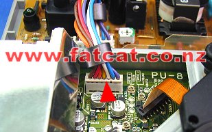
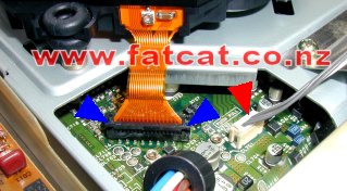
| Disconnect the
Laser Power (4 way) cable from the Mainboard by pulling firmly in a upward
motion at the base of the connectors as shown by the Red arrow. To remove the Laser Drive (orange ribbon) cable, grasp the connector at each end as shown by the 2 Blue arrows, and carefully pull up, the connector will lift up a little bit freeing the ribbon cable. Now just simply lift the ribbon cable away from the connector. DO NOT wiggle the cables to remove, you will only damage the connector pins or lift away the connectors pins from the Mainboard. Carefully lift away the Laser Drive Unit and place aside in a safe place. |
|
||||||||||||||||||||||
| Step 4: Removal of the Controller Port Housing and Cable | |||||||||||||||||||||||
|
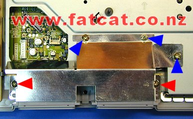
Remove the THREE screws as marked with the Blue arrows. Notice that
these short screws. Remove the TWO screws as marked with the Red arrows. Then lift the Controller Port Housing off and place aside. Important: When you re-assemble the Controller Port Housing ensure that you only use the short screws for those THREE Blue locations, otherwise you can damage any components below on the Mainboard. |
|
||||||||||||||||||||||
|
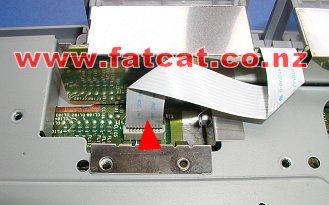
Disconnect the
White Ribbon cable from the Mainboard by pulling firmly in a upward motion at
the base of the connector. DO NOT wiggle the cable to remove, you will only damage the connector pins or lift away the connectors pins from the Mainboard. Now lift off the Controller Port Housing and place aside. |
|
||||||||||||||||||||||
| Step 5: Removal of the Earth Strap | |||||||||||||||||||||||
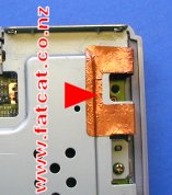
| Just
simply lift the copper tape in one corner and peel back towards the right
hand side of the case. Some SCPH 1002's may not have this tape. When you re-assemble your SCPH 1002 you may find that the tape may not stick to well, you can heat it a little with a hot air gun or hair dryer. But do not get worried if it will not stick down, it is it is not important. |
|
||||||||||||||||||||||
| Step 6: Removal of the Metal Base Plate | |||||||||||||||||||||||
| Once
you have removed the Laser Drive unit, Controller Port Housing and the Earth
strap you need to remove the FIVE
screws as indicated by the Red arrows that hold the metal base
plate down. Grab the metal plate, lift away and place aside. |
|
||||||||||||||||||||||
| Step 7: Removal of the Mainboard | |||||||||||||||||||||||
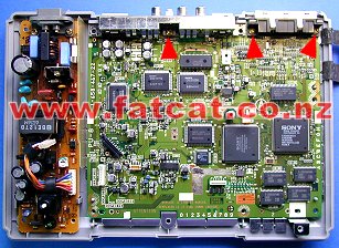
| Remove the
THREE screws as indicated by the Red arrows. Then
just simply lift the Mainboard away from the bottom case. |
|
||||||||||||||||||||||
| Step 8: What Mainboard to I have and what Installation Guides do I use? | |||||||||||||||||||||||
|
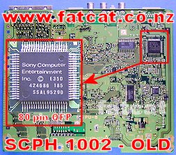
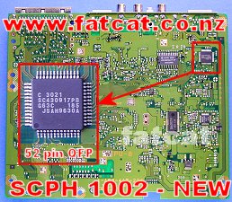
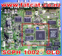
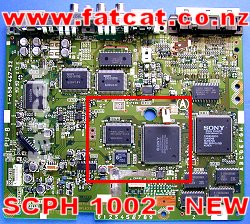
With the SCPH 1002's there were two different Mainboard's released.
You need to identify what version of the Mainboard you have so you can use the
correct installation guides. Installation wise there is not to much difference just in a few different connection points. To check what guides and diagrams to use look at the Red boxes on the photos below. Modchips - All Modchips are installed on the bottom side of the board. Check if the chip in the Red box in the photos is the same as on your Mainboard, the OLD board has the 80 Pin QFP package and the NEW board has the 52 Pin QFP package. Use the appropriate guides and diagrams. Colour Correction Module - The Colour Correction Module is installed on the top side of the board. Check if the chips in the Red box on the photos are the same as your Mainboard and use the appropriate guide and diagrams. |
|||||||||||||||||||||||
|
|||||||||||||||||||||||
| Re-Assembly of your PlayStation SCPH 1002 | |||||||||||||||||||||||
| Just simply
reverse the disassembly process starting at Step 7. Ensure that you push all cables firmly into the respective sockets. Any questions relating to this guide please email techsupport@fatcat.co.nz |
|||||||||||||||||||||||