| What is the purpose of a Colour Correction Module? | |||||||||
|
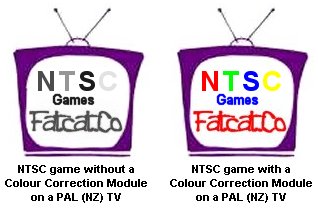
When you load NTSC (USA/JAPAN) game and display it on PAL (NZ) TV system the
picture will be displayed in Black and White as in the left TV picture below.
With the installation of a Colour Correction Module this will correct the
problem and allow the NTSC game to be displayed in Colour as in the right TV
picture.
|
|||||||||
| Minimum equipment required | |||||||||
|
Philips #2 or Medium Philips head screwdriver. Soldering Iron 15w/25w Solder Small Jewellers screwdriver Hot Glue Gun (optional) Insulated Tape Clean Work Area Time - Take your time |
|||||||||
| Step 1: Indentify and Disassembly of your PlayStation | |||||||||
|
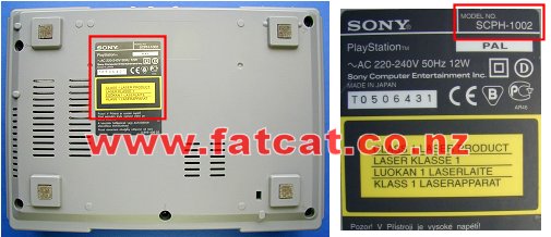
Before installing the Colour Correction Module ensure that your PlayStation is a model SCPH 1002, turn it over and look at the label on the bottom of the case as shown below. On the top right corner of the label it will indicate what model you have.
Use the SCPH 1002 Disassembly Guide - Then proceed to Step 2. |
|||||||||
|
|||||||||
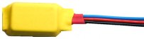
| Step 2: Familarise yourself with the Colour Correction Module | |||||||||
You will have received 1 x Pre Assemble and tested Colour Correction
Module (CCM) with double sided sticky pad, and a piece of Kynar wire. The
wires on the CCM have been cut to the correct length and tinned.
|
|
||||||||
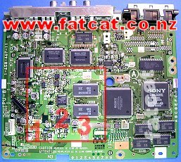
| Step 3: Locate Installation Area on Mainboard | |||||||||
|
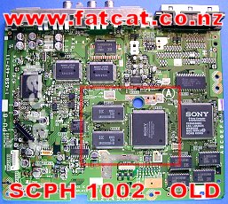
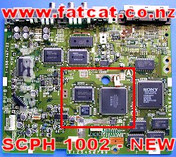
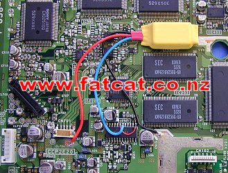
With the Mainboard topside up. The area enclosed by the Red box is where
the installation is to be carried out. 1. Red (+5Volts) Wire connection location 2. Blue (Freq) Wire connection area 3. Black (Ground) Wire connection area |
|
||||||||
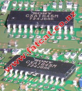
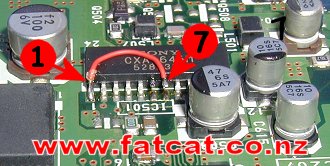
| Step 4: Lift 2 pins on the CXA 1645M Video Encoder Chip | |||||||||
| Okay
this is the trickiest part and takes the most care. The CXA 1645M Video
Encoder chip is the large chip located in top right corner as in the
picture in Step 3. You have to carefully lift PIN 6 and PIN 7 up off the Mainboard as in the picture to your right. I use a small jewellers screwdriver and place the blade between the pin and the Mainboard, apply your soldering iron to the pin and carefully using the adjacent pin as a lever to lift the pin up slowly. Repeat for the other pin |
|
||||||||
| Once
you have lifted up both PIN 6 and PIN 7 on the Video Encoder
chip, ensure that the
pins are completely lifted away from the Mainboard and no solder is
bridging the pins to the Mainboard as in the picture on the right. The example in the photo is from a SCPH 5502, it uses the same chip and the same pins. Just a different mainboard. |
|
||||||||
| Step 5: Solder in the Wire Link on the CXA 1645 Video Encoder Chip | |||||||||
| Tin PIN 1 and PIN 7 with a bit of solder. Using the piece of Kynar wire supplied, solder one end of the wire to PIN 7 and the other end to PIN 1 as shown in the picture. |
|
||||||||
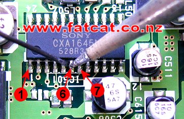
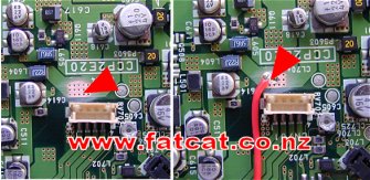
| Step 6: Connection of the RED (+5v DC) wire | |||||||||
|
Scrape
the area indicated with a RED arrow with a sharp blade, fine emery paper
or ideally with a Fiberglass pen to remove the "Solder Resist" coating on
the surface of the Mainboard. Tin the area you cleared with a bit of
solder and finally solder the RED wire to that
area. Ensure the no solder or any of the RED wire is touching the surround area on the board. |
|
||||||||
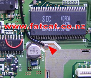
| Step 7: Connection of the BLACK (Ground) wire | |||||||||
| You
will probably will not need to tin the area indicated by the RED arrow as
there should be plenty of solder already, other tin with a bit of solder. Now just simply solder the BLACK wire to the area indicated with the RED arrow. Ensure the no solder or any of the BLACK wire is touching the surround area on the board. |
|
||||||||
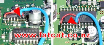
| Step 8: Connection of the BLUE wire to the CXA 1645 Video Encoder chip | |||||||||
| Tin
PIN 6 with a bit of solder, then solder the
BLUE wire to PIN 6 as shown on the
picture. I use a hot glue gun and squirt a bit of glue over the connection, to give it a bit more mechanical support to reduce any stress on the pin. Ensure that the wires from Pins 6 and 7 are not touching each other or the surrounding Pins or Mainboard. |
|
||||||||
| Step 9: Mounting the Colour Correction Module | |||||||||
|
Remove the protective cover from the double side tape on the bottom of the
Colour Correction Module and stick down on to the Mainboard as shown in
the photo. Do not put any un-necessary strain on the BLUE wire. It is a good idea to tape the wire down to the Mainboard to reduce the chance of wires getting pinched when re-assembling. PLEASE DOUBLE CHECK YOUR WORK AND ENSURE THE WIRES ARE GOING TO THERE CORRECT POINTS AND THERE ARE NO SOLDER BRIDGES ON THE VIDEO ENCODER CHIP BEFORE PROCEED TO THE NEXT STEP. |
|
||||||||
| Testing and Trouble Shooting | |||||||||
| To test your
Colour Correction Module installation, insert and load up a NTSC
(NTSC/JAPAN) game as you normally do, and you should see it being display
in glorious colour, if so well done. Still in Black and White? Check to ensure that: - You have lifted the correct pins on the CXA1645 Video Encoder chip in Step 4 - You have installed the wire link on to the CXA1645 Video Encoder Chip as in Step 5 - Good solder connection of the BLUE wire to Pin 6 as in Step 8 - Pin 6 has not broken away from the Video Chip - The +5VDC and Ground Wires are connected to the right place as shown on the diagram as in Steps 6 and 7. - You have not pinched any wires when re-assembling, especially when routing the wires out between the Mainboard and the bottom part of the case. PlayStation Shutting Down
when turning on? Picture Fuzzy?
Picture Rolling / Flickering? |
|||||||||