IMPORTANT: READ THIS
GUIDE THOROUGHLY BEFORE INSTALLATION! Please read Disclaimer Any questions relating to this guide please email techsupport@fatcat.co.nz |
Xbox LPC Modchip Installation Guide for
Xbox Versions 1.0, 1.1 and 1.2
IMPORTANT: READ THIS
GUIDE THOROUGHLY BEFORE INSTALLATION! Please read Disclaimer Any questions relating to this guide please email techsupport@fatcat.co.nz |
| Introduction | |
|
Please note this is only a draft copy of
this document as at 14 February 2003. I still need to add a few more section and
photos, but the document as it is will enable you to install your LPC modchip. Full document should be
uploaded in a few days time. |
|
| Minimum equipment required | |
|
Soldering Iron and solder Solder sucker or De-soldering Braid (for v1.0 Xbox's only) Clean Work Area Time - Take your time |
|
| The LPC Modchip | |
|
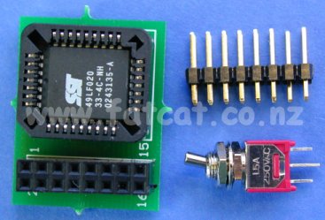
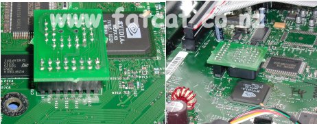
The picture on the right shows the LPC Modchip, Header pins and Switch. LPC Modchip (left) A PCB with a Flash memory chip and a 2x8 Header socket. This plugs into the Header Pins. Header Pins (top right) The 2x8 Header Pins are soldered on the the Xbox mainboard and the LPC modchip plugs into this. Switch (bottom right) - The Switch is optional and is used to dis-able the LPC modchip and re-store the Xbox to it's original state if need be ie To use Xbox Live when it comes to New Zealand. |
|
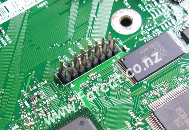
| Step 1: Locating the LPC Port and Header Pin Connection Points | |
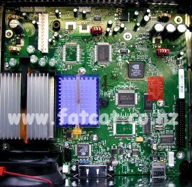
| The
Header Pins have to be soldered into the LPC Port on the mainboard. This
area is located where the RED rectangle is. Please note if you have a V1.0 mainboard you will have a fan where the BLUE rectangle is located. The mainboard used in this picture is from a V1.1 Xbox and this board has a heat sink instead of a fan. |
|
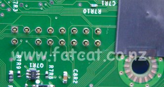
|
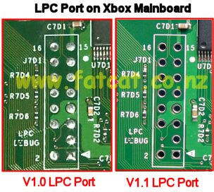
Close up picture of the LPC Port. The LPC port on the left hand side of the picture is from a V1.0 Xbox and has the Header Pin holes filled with solder. You will have to use a Solder Sucker or De-solder Braid to remove the solder from the holes. The LPC port on the right hand side is from a V1.1 Xbox and the the Header Pin holes will not filled with solder - Lucky you :o) |
|
|
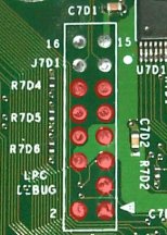
For you V1.0 Xbox owners. To make like a little easier on you. You only have the remove the solder from the 11 holes marked with a RED circle. You will have to snap of the last two rows off on the header pins so that they will fit in. The last two rows are are at the opposite end to the end that has a pin missing.) If you are really lazy you can just solder the headers pins on top of the holes without out removing the solder. |
|
| Step 2: Installing and Soldering Header Pins | |
| Place the Header Pins into the holes as shown in the picture. |
|
| Turn
the mainboard over and solder the Header Pins into place on the bottom
side. If the Header Pins are a loose fit in the holes, you may have to do a little jiggling to hold the Pins in place while you turn the mainboard over and get the first pin soldered in. Once all pins have been soldered in turn the mainboard back over to the top side. |
|
| Step 3: Installation of the D0 Jumper or a Dis-able Switch | |
| To
allow you LPC Modchip to take control over your Xbox you need to
connection the D0 point to Ground. Note: YOU MUST DO EITHER: A - Connect a wire link between D0 and Ground Point or B - Install a switch between D0 and the Ground Point If you do not do A or B then your Modchip will not function. The picture shows you the location of the two points. Please take care when soldering the wire to the D0 connection points. This is the point that causes the most problem when installing a modchip into the Xbox no matter what chip you use. I have seen a Matrix chip pogo pins damaging this connection, to much heat and people lifting the via/track of the board. And is the source of many repairs I have had to carry out for people. You have been warned. There is an alternative point on the bottom side. I will upload this picture when I upload the full document. You have to the option of either: Wire Link Soldering a wire link from the D0 point to the Ground point. If you solder the wire link in place your Modchip is en-able all the time. Dis-able Switch By installing a switch between the D0 point and the Ground point will enable you to turn your LPC modchip on and off. Why would you want to turn your Modchip off? Main reason is if Microsoft get Xbox LIVE up and running in New Zealand and you connect to Xbox LIVE with a modchip en-able your Xbox will be BANNED for ever. |
|
|
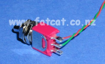
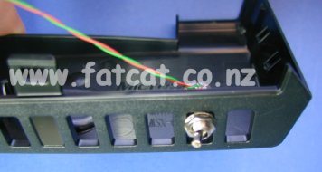
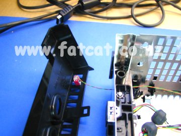
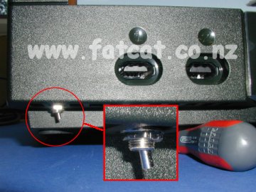
Additional Dis-able
Switch Information What sort of switch do you use? I use a Single Pole Double Throw (SPDT) miniature switch and I cut the length of switch lever down. Where do you fit the switch? I remove the front panel and fit the switch to this. See the picture, this is just a to give you an idea where to fit. It's a pain to remove the front panel, but is the best place to fit it with out have to cut holes etc into your Xbox. The front panel is clipped to the main case at either end and also held by three clips on the inside of the case. You will not have to remove any screws to remove the front panel - it's just a pain to unclip from the sides of the case.
Solder two wires to the switch. One wire is soldered to the centre leg and
the other wire is soldered to one of the legs. Then mount the switch to
the front panel as shown in the picture. |
|
|
|
|
| Step 4: Fitting the LPC Modchip | |
| You
just simply place the LPC Modchip over the Header Pins and Press down.
Ensure that the LPC Modchip has been in the correct position. Now re-assemble your Xbox and test. Troubleshooting section to come. |
|
Any questions relating to this guide please email techsupport@fatcat.co.nz |
|