| Messiah Version 4
Main Board
Installation Diagrams |
I have verified that the following installation
diagrams below will work with all New Zealand released Version 4 main
board. The
Version 4 main board will normally be fitted in the SCPH 35002.
To view some installation photos - click
here
Any questions etc - Email Andrew at:
messiah@fatcat.co.nz
Back to the Messiah Page |
| |
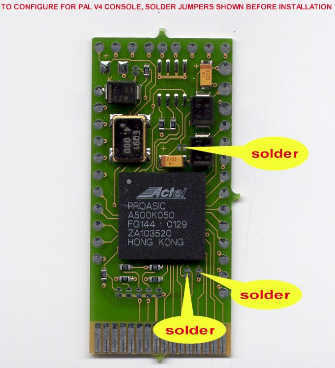
| Configuration Jumper
Settings |
|
|
|
Important: Do this first before you
start your install. Ensure that you solder all 3 jumpers. Failure to do so
may damage your Messiah chip.
|
| |
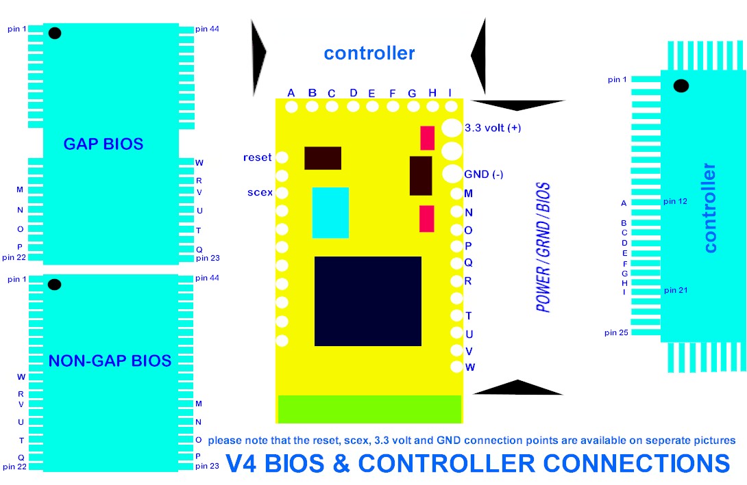
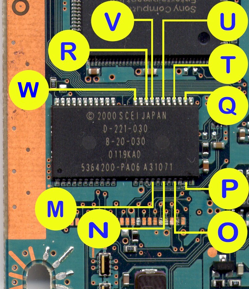
| Messiah Connection
Points |
|
|
Pictorial view of the Messiah connection pads
and the associated points on the Bios and Controller chips. Use this diagram
to check and recheck that you have soldered the wires to the correct
points.
|
|
|
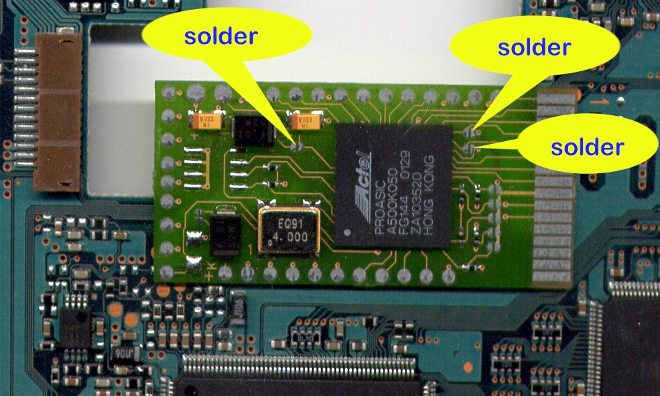
| Messiah Location on
the Main Board - Top Side of Main Board |
|
|
|
The Messiah is stuck down with double sided
tape half hanging over the hole for the Laser Drive on the top side of the main board.
|
| |
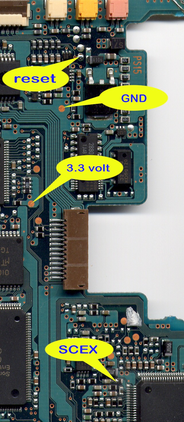
| V3 - Power, Ground,
Reset & SCEX Connection Points - Top Side of Main Board |
 |
|
All the connection points are located near the
hole for the Laser Drive on
the top side of the main board. Use 30swg wire wrap wire for the SCEX and
Reset connections and use light hook-up wire for the +3.3VDC and Ground
connections.
|
| |
| Gap Bios Connections - Top
Side of main board |
|
|
|
The Bios chip is located on the top side of the
main board along the top edge about half way along. Use 30swg wire wrap wire for these
10
connections.
|
|
|
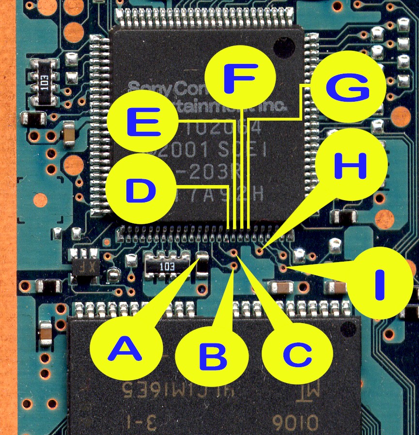
| Controller Points
- Top Side of Main Board |
|
|
|
The Controller chip located on the top side
along the top edge right hand corner of the main board. Use 38swg enamel wire for the
point "D", "E", "F", "G" and
"H"
connections to the Controller chip and you can use either 30swg wire wrap wire
or 38swg enamel wire for point "A", "B", "C"
and "I" connections to the tracks on the main board. You will need
to use a fibreglass pen to remove the solder resist over the connection
points to get a good joint. Ensure that you have the experience in
soldering to surface mount components before you even consider attempting to
carry out these connections.
|
|
|
| RGB and NTSC-PAL Fix -
Top Side of Main Board |
|
Picture to Come - Same connections as V3
|
RGB Fix: (top part of the diagram) is
required if you intend on using a SCART/EURO cable instead of the standard
AV cable. SCART/EURO connectors are general more associated with the
Europe/UK TV systems. If you do not do this you may end up with a green
picture on your TV when viewing DVD movies. I only do this if customer wants
it.
NTSC-PAL Colour Correction: (bottom part of the diagram) is required
if you intend on play NTSC (USA/Japan) games or view NTSC movies. Simply
just solder across the 2 pins. I do this as standard on all installations.
If you do not do this fix NTSC games will be displayed in Black and White on
PAL TV's unless you have a nice NTSC compatible TV system :o)
|