| Messiah Version 3
Main Board
Installation Diagrams |
I have verified that the following installation
diagrams below will work with all New Zealand released Version 3 main boards. The
Version 3 main board will normally be fitted in the SCPH 30002. Please
note there are 3 variants of the Bios chip. Please ensure that you
use the correct diagram for your version of the Bios.
To view some installation photos - click
here
Any questions etc - Email Andrew at:
messiah@fatcat.co.nz
Back to the Messiah Page |
| |
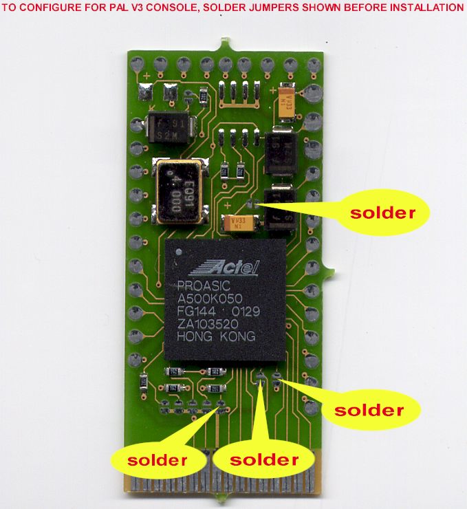
| Configuration Jumper
Settings |
|
|
|
Important: Do this first before you
start your install. Ensure that you solder all 4 jumpers. Failure to do so
may damage your Messiah chip.
|
| |
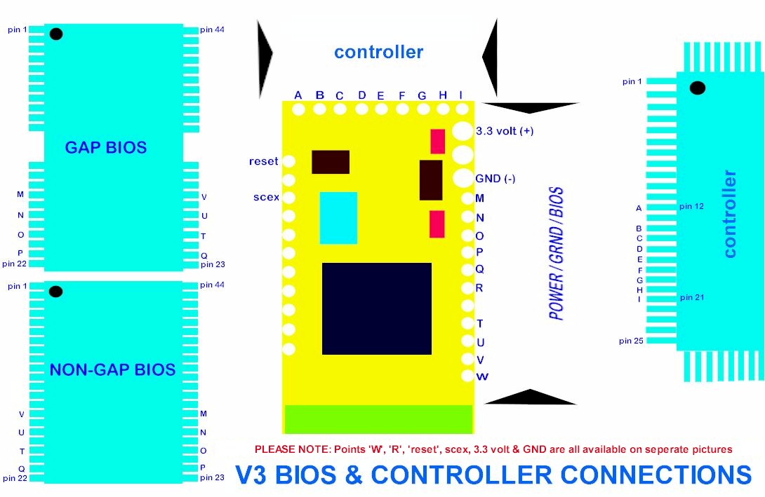
| Messiah Connection
Points |
|
|
Pictorial view of the Messiah connection pads
and the associated points on the Bios and Controller chips. Use this diagram
to check and recheck that you have soldered the wires to the correct
points.
|
|
|
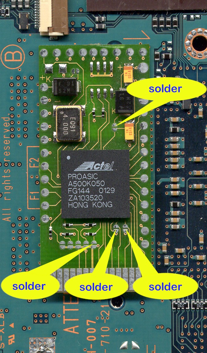
| Messiah Location on
the main board - Top Side of Main Board |
|
|
|
The Messiah is stuck down with double sided
tape onto the open space on the topside of the main board. You can't miss it
- it's the only bit of real estate left where the chip can fit nicely onto
the main board :o)
|
| |
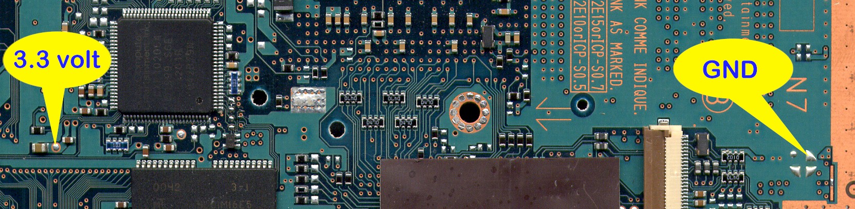
| V3 - Power and Ground
Connection Points - Top Side of Main Board |
 |
|
Both of the connection points are located on
the top side of the main board. Use light hookup wire for these two connections
|
| |
| SCEX Connection Point -
Bottom Side of Main Board |
|
|
|
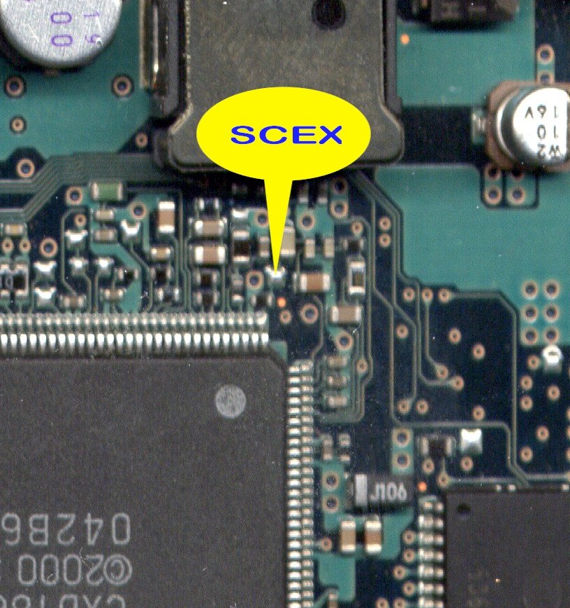
This connection point is located on the bottom
side of the main board. You have to remove the 4 machine screws that hold the heatsink in place. Remove the heatsink to expose the SCEX connection
point. Use 30swg wire wrap wire for this connection and feed the wire
through one of the holes in the main board, but not the screw holes for the heatsink!!!
Click here to see a photo showing the SCEX connection and the hole it is
routed through. |
|
|
| Bios Chip - Top
Side of main board |
|
|
|
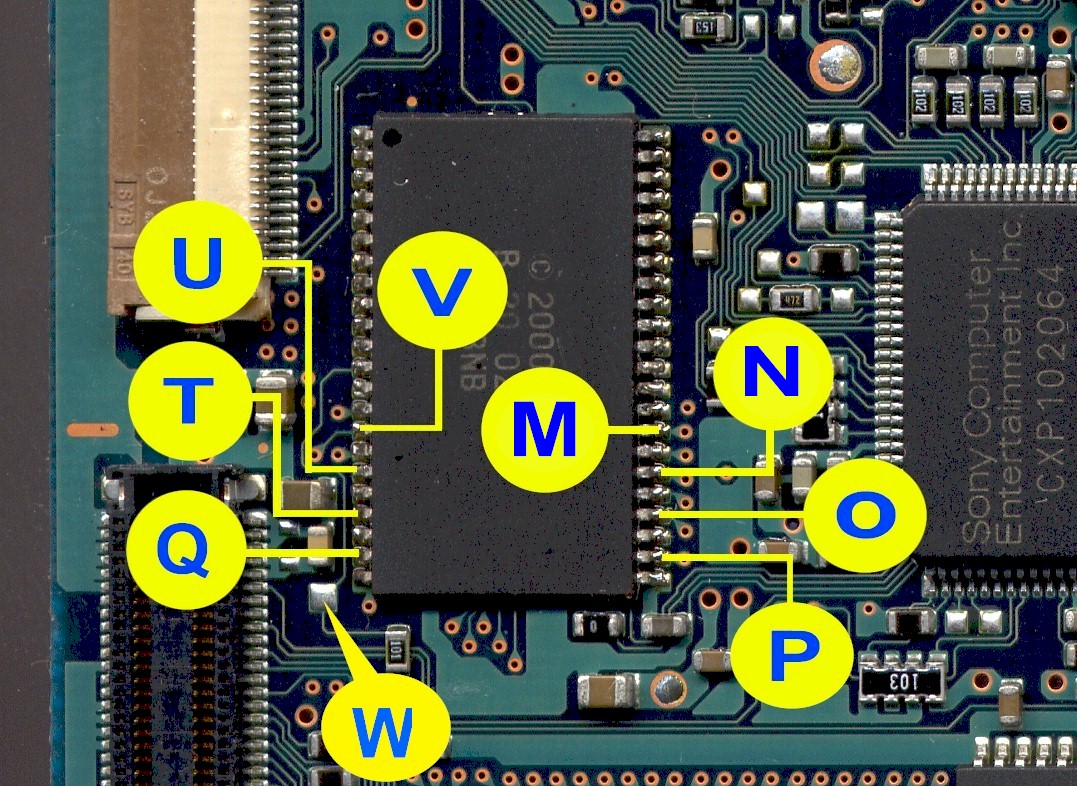
This Bios on the top side of the main board is
generally in the earlier releases of the PS2's in NZ. It is located over by
the Expansion Port connector. Use 30swg wire wrap wire for these 9
connections.
|
|
|
| No Gap Bios - Bottom
Side
of Main Board |
|
|
|
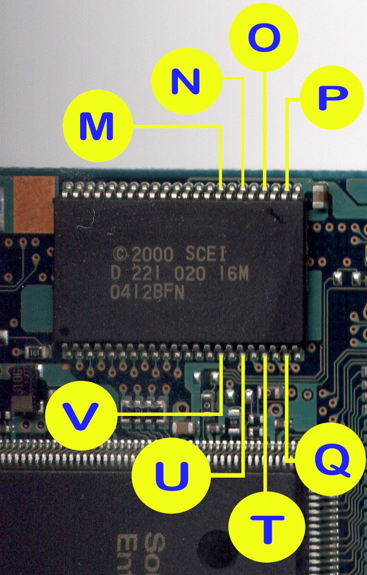
This Bios is located on the along one of the
edges on the bottom side of the main board. Use 30swg wire wrap wire for all 8
connections and route the wires through one of the hole on the main board so
they appear on the top side. The 9th connection "W" point is
located on the top side of the main board, see diagram further down.
|
|
|
| No Gap Bios -
Bottom Side of Main Board |
|
|
|
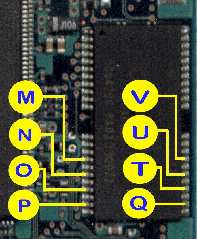
This Bios is located on the along one of the
edges on the bottom side of the main board. This is generally associated
with the later versions of the SCPH 30002 models. Use 30swg wire wrap wire
for all 8 connections and route the wires through one of the holes on the
main board so the appear on the top side. The 9th connection "W"
point is located on the top side of the main board, see diagram further
down.
|
|
|
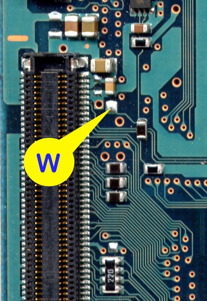
| "W" Point for
the Gap / No Gap Bios - Top Side of Main Board |
|
|
|
This "W" connection point is ONLY for the Gap and
No Gap Bios that located on the bottom side of the main board. This W
connection point is located on the top side of the main board next to the
Expansion Port connector. Use 30swg wire wrap wire for this connection.
|
|
|
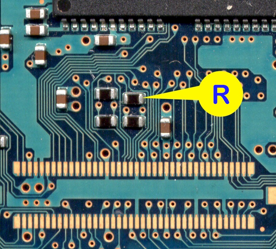
| "R" Point -
Top Side
of Main Board |
|
|
|
This point is located over by the Controller
chip on the top side of the main board. Use 30swg wire wrap wire for this
connection.
|
|
|
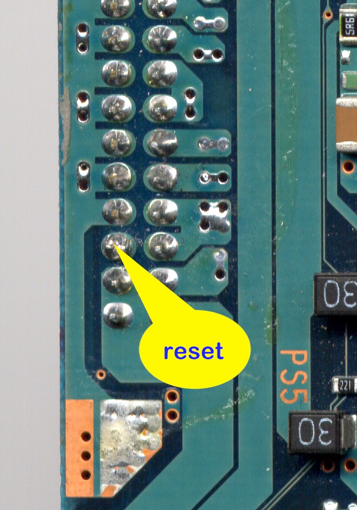
| Reset Point - Top Side
of Main Board |
|
|
|
This connection point is locate along one of the
edges near the corner that has 4 large holes on the top side of the main
board. Use 30swg wire wrap wire for this connection.
|
|
|
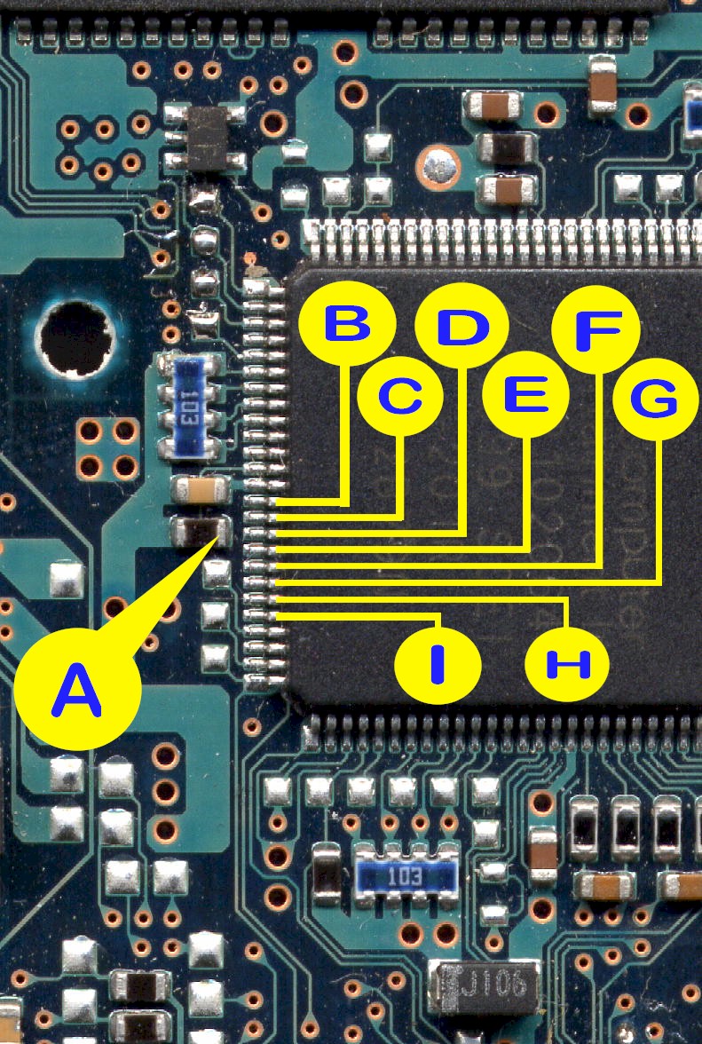
| Controller Points
- Top Side of Main Board |
|
|
|
The Controller chip locate by the group of 3
connectors in one corner of the main board. Use 38swg enamel wire for the 8
connections to the Controller chip and 30swg wire wrap wire for the
"A" point connection. Ensure that you have the experience in
soldering to surface mount components before you even consider attempting to
carry out these connections.
|
|
|
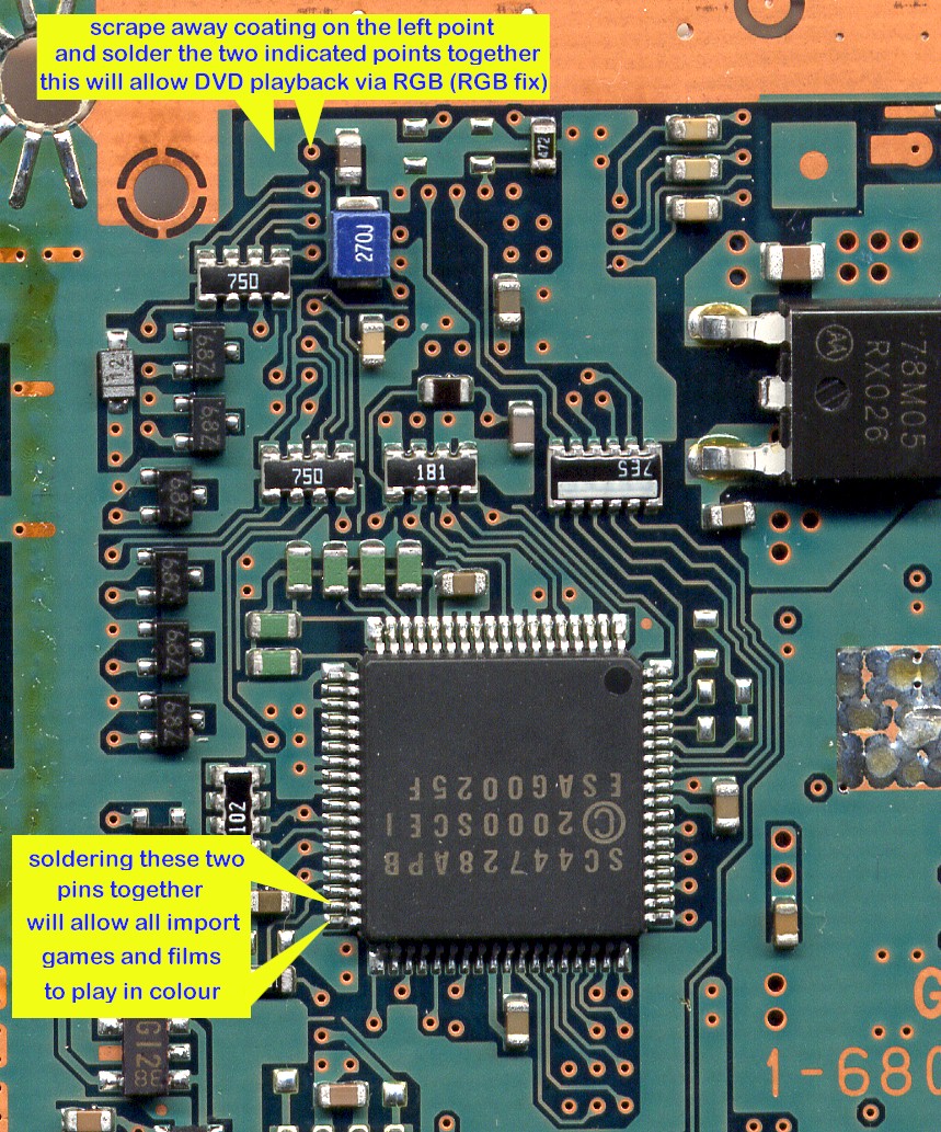
| RGB and NTSC-PAL Fix -
Top Side of Main Board |
|
|
RGB Fix: (top part of the diagram) is
required if you intend on using a SCART/EURO cable instead of the standard
AV cable. SCART/EURO connectors are general more associated with the
Europe/UK TV systems. If you do not do this you may end up with a grren
picture on your TV when viewing DVD movies. I only do this if customer wants
it.
NTSC-PAL Colour Correction: (bottom part of the diagram) is required
if you intend on play NTSC (USA/Japan) games or view NTSC movies. Simply
just solder across the 2 pins. I do this as standard on all installations.
If you do not do this fix NTSC games will be displayed in Black and White on
PAL TV's unless you have a nice NTSC compatible TV system :o)
|