IMPORTANT: READ THIS
GUIDE THOROUGHLY BEFORE DISASSEMBLY! Please read Disclaimer Any questions relating to this guide please email techsupport@fatcat.co.nz |
Disassembly Guide for PlayStation Model SCPH
900x.
IMPORTANT: READ THIS
GUIDE THOROUGHLY BEFORE DISASSEMBLY! Please read Disclaimer Any questions relating to this guide please email techsupport@fatcat.co.nz |
| Identifying your model of PlayStation | |
|
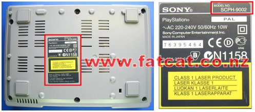
Before dismantling your PlayStation turn it over and look at the label on the bottom of the case as shown below. On the top right corner of the label it will indicate what model you have. This guide is for the model SCPH 900x, where x is either 2 (PAL, NZ/AUS/UK), 1 (USA) or 0 (JAP). If this model number is different do not use this guide. All New Zealand and Australian models will be marked as SCPH 9002
|
|
| Minimum equipment required | |
|
Philips #2 or Medium Philips head screwdriver. Container to place screws etc in Clean Work Area Time - Take your time |
|
| Step 1: Removal of the top half of the case | |
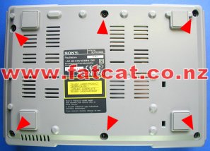
| Unplug all cables, controllers, memory cards etc from PlayStation. Remove any CD from PlayStation. Turn PlayStation over and remove the SIX Black screws as indicated by the Red arrows that hold the 2 halves of the case together using a Philips screwdriver. |
|
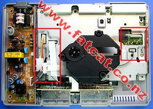
Turn PlayStation back over and lift away the top half of the case. Now you should see what is shown in the photo. Red box on left hand side are the cable clip, power and controller port cables. Red box on right hand side are the Laser Drive cables. The Black thing in the middle is the Laser Drive Unit. The Power supply is the unit located on the left hand side and the Controller Ports are in the front. WARNING: LETHAL VOLTAGES Do not leave your PlayStation connection to the 220Vac Mains power supply with the cover removed and PlayStation Power supply unit exposed!! |
|
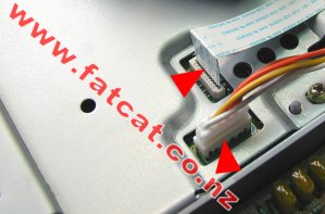
| Step 2: Removal of the Cable Clip and Disconnection of the Power and Controller Port cables | |
| The
Power and Controller Port cables are held in place with a white plastic
cable clip. To remove the cable clip, squeeze the sides together and lift
up. Up may have to wiggle it when lifting up to aid in removal. Place
aside. |
|
| Disconnect the
Power cable (4 way cable) and the Controller Port cable (white
ribbon cable) from the Mainboard by pulling firmly in a upward motion at
the base of the connectors. DO NOT wiggle the cables to remove, you will only damage the connector pins or lift away the connectors pins from the Mainboard. There is no need to completely remove the cables from the other end, just move the cables to one side and you do not need to remove the Power or Controller port unit. |
|
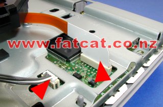
| Step 3: Disconnection of the Laser Drive cables and Removal of the Laser Drive | |
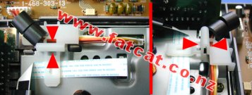
| Disconnect the
Laser Power cable (4 way cable) and the Laser Controller cable
(yellow ribbon cable) from the Mainboard by pulling firmly in a upward
motion at the base of the connectors. DO NOT wiggle the cables to remove, you will only damage the connector pins or lift away the connectors pins from the Mainboard. Carefully lift away the Laser Drive Unit and place aside in a safe place. |
|
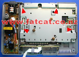
| Step 4: Removal of the Metal Base Plate | |
| Once
you have removed the Laser Drive unit, you need to remove the FOUR
screws as indicated by the Red arrows that hold the metal base
plate down. Grab metal plate at rear and lift away, you will have to carefully wiggle it, to assist in it's removal. |
|
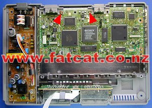
| Step 5: Removal of the Mainboard | |
| Remove the TWO screws as indicated by the Red arrows. Then just simple lift the Mainboard away from the bottom case. |
|
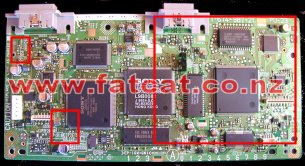
| Once
you have remove the Mainboard you are ready to carry out your installation
work. All the ModChip
work is carried out in the area indicated by the top left hand corner and
right hand red box on the top side of the Mainboard. |
|
| Installing a Modchip or Colour Correction Fix into your PlayStation SCPH 9002 | |
| Okay your are now
ready to carry out the installation work, please select the appropriate
Installation Guide for your ModChip or Colour Correction Module Standard ModChip (4 Wire) Installation Guide Stealth Modchip (7 Wire) Installation Guide Colour Correction Module Installation Guide |
|
| Re-Assembly of your PlayStation SCPH 9002 | |
| Just simply
reverse the disassembly process starting at Step 5. Ensure that you push all cables firmly into the respective sockets. When it comes to Step 2 and reconnecting the Controller Port cable you may want to place a piece of tape from the metal plate across the Controller port cable/connector to the Controller port housing, as this cable as be known to work it's way loose, if you have been heavy handed. Any questions relating to this guide please email techsupport@fatcat.co.nz |
|